

How to Choose Solar Mounting Rails for Different Panel Sizes(2026)

Last Updated: November 17th, 2026
Author: Devi Huang | International Sales Team, ALV(E-mail address:sales@xmalv.com)
Devi Huang is part of the international sales team at ALV, a manufacturer of solar mounting systems and aluminum profiles. She works with EPC contractors, distributors, and project developers worldwide, helping customers choose the right mounting solutions based on project requirements, local standards, and budget.
Introduction
Choosing the right solar mounting rails is an important step in designing a safe, durable, and cost-effective photovoltaic (PV) mounting system. Solar panels are available in different dimensions, frame thicknesses, weights, and power ratings. A rail suitable for one module may not provide the correct support for another.
For solar installers, engineering contractors, distributors, and EPC companies, selecting the right rails involves more than matching the rail length to the panel size. You also need to consider the module’s approved mounting zones, rail span, structural loads, roof type, attachment spacing, and compatibility with clamps and fasteners.
The key principle is simple: choose solar mounting rails based on the complete mounting-system design, not panel dimensions alone.
In this guide, we explain how to select aluminum solar mounting rails for different panel sizes, what technical specifications to check, and how to avoid common design and installation mistakes.
1. Why Panel Size Matters When Choosing Solar Mounting Rails
Solar modules vary considerably in size. Compact modules may be used in residential or specialized applications, while larger-format modules are common in commercial and utility-scale installations.
A larger module can have a longer frame, a wider surface area, or a different arrangement of mounting holes. These characteristics influence rail layout, clamp positioning, structural loading, and the number of supports required.
The following examples are illustrative dimensions, not specifications for every module in the category.
| Illustrative module category | Example dimensions (L × W) | Main selection consideration |
| Compact residential | 1,762 × 1,086 mm | Module mounting zones and roof layout |
| Standard commercial | 2,278 × 1,134 mm | Approved support positions and rail span |
| Large-format | 2,384 × 1,303 mm | Structural verification, clamp zones and support layout |
Actual module dimensions vary by manufacturer, model, and product generation. Always confirm the module datasheet before designing a mounting system.
How panel dimensions affect rail selection
Module length: Determines the array layout, clamp locations, and how modules fit along a row. Depending on whether modules are installed in portrait or landscape orientation, the relevant dimension along the rail changes.
Module width: Influences module spacing, mid-clamp positioning, and the layout of adjacent panels. It also affects the overall geometry of the array.
Module weight and surface area: Larger modules may introduce different dead loads and wind forces. The final rail and support design must account for these loads and the manufacturer’s installation requirements.
Frame thickness and mounting holes: These affect clamp compatibility and, for approved bolted systems, fastener positioning.
A correct rail selection therefore begins with the actual module specification, rather than an assumption that all panels of similar wattage use the same mounting hardware.
2. Understand the Main Types of Solar Mounting Rails
Aluminum rails are widely used in rooftop PV mounting systems because they offer a useful combination of low weight, corrosion resistance, and ease of handling. However, the appropriate rail profile depends on the application and the complete system design.
Standard aluminum solar rails
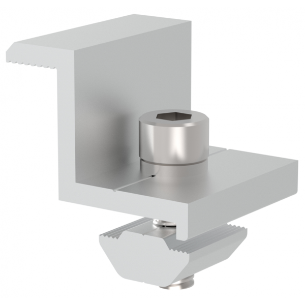
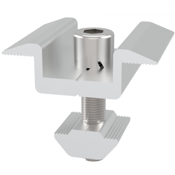
Standard rails are commonly used in residential and commercial rooftop installations. They support PV modules through compatible mid-clamps and end-clamps and connect to roof attachments or mounting feet.
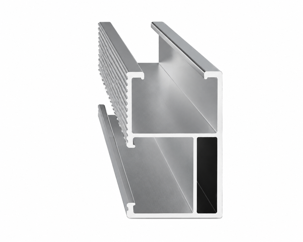
When choosing a standard rail, check its cross-sectional dimensions, material and temper, moment of inertia, section modulus, approved span, and compatible accessories. Two rails that look similar may have different structural capacities.
Heavy-duty aluminum rails
Heavy-duty profiles may be appropriate for applications requiring longer support spans or higher structural capacity. They should not be selected simply because a panel is larger.
The required capacity depends on the design loads, rail geometry, attachment spacing, and the strength of the complete load path. A heavy-duty rail that is inadequately supported can still fail to meet the project’s requirements.
Short-rail or rail-less mounting solutions
Some metal-roof mounting systems use short rails or specially designed brackets instead of conventional continuous rails. These solutions may reduce material use or simplify installation in suitable applications.
However, their suitability depends on roof construction, module mounting requirements, wind loads, and the tested or engineered system configuration.
For ALV customers, the most appropriate solution may be a standard aluminum rail, a reinforced profile, or a roof-specific mounting system. The choice should follow the project requirements rather than a universal rule.
3. How to Choose Rails for Different Panel Sizes
A. Compact residential panels
Compact modules are often easier to arrange on small roofs with multiple obstructions, roof windows, or irregular roof areas.
For these installations, consider:
- Rail compatibility: Confirm that the rail accepts the selected mid-clamps and end-clamps.
- Roof attachment positions: Ensure the attachments connect to suitable structural members or approved roof-mounting points.
- Installation flexibility: Consider whether the rail system allows convenient adjustment and alignment.
- Material efficiency: Avoid excessive rail overhang or unnecessary rail length while maintaining the required structural capacity.
A compact panel does not automatically require a smaller or weaker rail. In high-wind areas, exposed roof locations, or projects with challenging support spacing, structural requirements may govern the rail selection.
B. Standard commercial panels
Commercial rooftop systems often use repeated module layouts. Consistent rail profiles and standardized accessories can simplify installation and purchasing.
For these projects, focus on:
- Maintaining consistent rail alignment across the array.
- Verifying the permitted module clamp zones.
- Checking rail deflection and strength at the proposed support spacing.
- Coordinating rail lengths with module rows and roof attachment locations.
- Minimizing unnecessary joints and offcuts without compromising design requirements.
For large commercial installations, a small improvement in installation efficiency per module can become meaningful across hundreds or thousands of modules. However, material savings should always be evaluated against engineering requirements and installation labor.
C. Large-format solar panels
Large-format modules require particular attention to their mounting instructions and structural design. Their dimensions, mass, and wind-exposed area may differ substantially from those of smaller modules.
Before selecting a rail, verify:
- The manufacturer’s approved mounting positions and clamp zones.
- The maximum permitted distance between rail supports under the proposed loading conditions.
- Rail bending, deflection, and connection strength.
- The capacity of roof attachments, fasteners, and supporting structures.
- Compatibility with the module frame and the complete mounting system.
Important: A larger panel does not automatically mean that the rail must run along the panel’s longest edge. Rail orientation depends on the approved module mounting configuration, array layout, and mounting-system design.
The final rail profile and support spacing should be confirmed through engineering calculations and applicable manufacturer documentation.
4. Portrait vs. Landscape: How Orientation Changes Rail Layout
Panel orientation changes the relationship between module dimensions, rail direction, and clamp positions.
Portrait installation
In portrait orientation, the shorter side of a typical rectangular module runs across the row, while its longer side runs in the perpendicular direction. In a common two-rail arrangement, rails cross the module’s width at the approved mounting zones along its length.
The exact rail position must follow the module manufacturer’s mounting instructions.
Landscape installation
In landscape orientation, the module is rotated by 90 degrees. This changes the positions of the approved mounting zones relative to the rail layout and may change the number or arrangement of rails required by a specific system.
Never assume that rotating a panel preserves the same support spacing or structural performance.
What should installers check?
Before finalizing the layout, confirm the module orientation, mounting-hole positions if applicable, permitted clamp zones, rail direction, and required support points. Also verify whether the selected clamps and rail connectors are approved for that configuration.
5. How to Calculate the Required Solar Rail Length
Rail length is a layout dimension, not a substitute for structural design.
For a simple row of modules, the approximate array length can be calculated from the module dimension along the row, the number of modules, and the gaps between them.
Formula:
Array length = (Number of modules × Module dimension along the row) + (Number of gaps × Gap width)
For example, assume a row contains eight modules, each with a dimension of 1,134 mm along the row, and the planned gap is 20 mm.
Array length = (8 × 1,134) + (7 × 20)
Array length = 9,072 + 140 = 9,212 mm
The approximate module-row length is therefore 9.212 m.
This is only a preliminary layout calculation. It does not include additional edge clearance, rail overhang, expansion gaps, connector requirements, or roof-specific restrictions. The final rail cut length must be determined from the actual mounting layout.
How many rails are required?
The number of rails is determined by the mounting configuration, not by panel dimensions alone. A typical system may use two rails per module row, but some module manufacturers or mounting systems require different arrangements.
For purchasing and material planning, calculate the total rail length from the approved layout, then account for rail segmentation, splice requirements, cut lengths, and installation waste.
Do not treat the number of modules multiplied by two as a universal rail-count formula.
6. How to Determine Rail Span and Support Spacing
Rail span is the distance between structural support points. It is one of the most important variables in determining whether a mounting rail is suitable for a particular project.
A longer span can increase the bending moment and deflection. For a simplified beam model under a uniformly distributed load, bending moment and deflection are strongly affected by span length. Actual PV rails, however, may experience distributed and concentrated loads, multiple support conditions, and different connection behavior.
For this reason, rail selection must be based on verified section properties and an appropriate structural model.
Key Factors Affecting Rail Span
- Rail profile: Cross-sectional shape, wall thickness, moment of inertia, and section modulus.
- Applied loads: Dead load, wind uplift and pressure, snow load, and applicable load combinations.
- Support conditions: Attachment spacing, connection stiffness, cantilever length, and rail splices.
- Allowable deflection: Project-specific serviceability criteria and module requirements.
- Connection capacity: The strength of clamps, fasteners, splices, brackets, and roof attachments.
There is no single rail span that is safe for every module size or project. The maximum permitted span must come from the relevant rail system’s engineering data or a project-specific calculation.
7. Consider Wind Load, Snow Load, and Local Standards
Solar mounting rails must perform under the environmental conditions of the installation site.
In the United States, ASCE/SEI 7-22 provides design provisions for hazards including wind, snow, rain, and other loads. The applicable adopted edition and local building requirements must be confirmed for each project.
For international projects, engineers should use the relevant local standards and project specifications.
Wind load
Wind can create uplift and pressure on modules, rails, clamps, and roof attachments. Roof-edge and corner zones can experience different pressures from interior zones.
The U.S. Department of Energy recommends mounting designs that follow appropriate module attachment requirements and use tested or adequately rated components for the expected conditions.
Snow load
Snow loading can create substantial downward forces and may vary with roof geometry, local climate, drifting, and array configuration. The rail and support system must be checked for the applicable design loads.
Coastal and corrosive environments
For coastal installations, consider corrosion resistance of the rail alloy, fasteners, clamps, and interfaces between dissimilar metals. Material compatibility and drainage details are important to long-term performance.
Aluminum rails can be a practical option in corrosive environments, but suitability depends on the alloy, finish, fasteners, exposure conditions, and maintenance requirements.
Module testing is not the same as rail-system approval
The IEC 61215 series covers design qualification and type approval testing for terrestrial PV modules. It does not, by itself, certify that any selected rail and mounting configuration is structurally suitable for a particular project.
Always evaluate the module and mounting structure as a compatible, engineered system.
8. Aluminum Rail Specifications Buyers Should Compare
When comparing solar mounting rails from different suppliers, do not focus on price per meter alone.
| Specification | Why it matters |
| Aluminum alloy and temper | Affects mechanical properties and suitability |
| Cross-sectional drawing | Confirms geometry and dimensions |
| Wall thickness | Contributes to section properties and strength |
| Moment of inertia and section modulus | Used in structural calculations |
| Rail mass per meter (kg/m) | Supports weight and material-cost calculations |
| Surface finish | Relevant to appearance and environmental exposure |
| Rail length and tolerances | Affect cutting, transport, and installation |
| Clamp and splice compatibility | Helps ensure correct system assembly |
| Engineering span tables | Support project-specific structural verification |
| Applicable test reports and documentation | Help verify suitability for the intended market |
For custom aluminum profiles, a technical drawing and the mass per meter are particularly useful for accurate costing. If these are unavailable, the supplier may need additional profile measurements or a sample before providing a reliable quotation.
A lower-priced rail is not necessarily more economical if it requires additional supports, incompatible accessories, or more installation time.
9. Common Mistakes When Choosing Solar Mounting Rails
Avoid these frequent errors:
1. Selecting rails based only on panel wattage. Two modules with the same rated power can have different dimensions, weights, frame designs, and mounting requirements.
2. Assuming longer rails are always better. Longer rails can reduce joints but may require different support spacing or structural verification.
3. Ignoring approved clamp zones. Clamping outside the module manufacturer’s permitted locations can compromise the installation and may affect product warranty conditions.
4. Choosing a rail without checking its section properties. Similar-looking extrusions may have very different stiffness and load capacity.
5. Overlooking the roof structure. The rail must transfer loads through the attachments into a suitable supporting structure. A strong rail alone does not guarantee a safe system.
6. Mixing incompatible components. Rails, clamps, splices, fasteners, and roof attachments should be verified for compatibility and the intended loading conditions.
7. Treating module certification as complete mounting-system validation. Module qualification does not replace structural calculations or verification of the complete mounting assembly.
10. Why Consider ALV Aluminum Solar Mounting Rails?
For EPC contractors, solar installers, distributors, and mounting-system manufacturers, a reliable rail supplier should provide more than a standard extrusion. Profile compatibility, consistent manufacturing quality, technical documentation, and project-specific support all contribute to a successful installation.
ALV specializes in photovoltaic mounting systems and aluminum profiles, covering rooftop, ground-mounted, and solar carport applications.
When evaluating ALV rails or custom aluminum profiles, project teams can focus on:
- Application-specific selection: Match rail profiles to module dimensions, mounting orientation, roof conditions, and project requirements.
- Aluminum profile options: Evaluate suitable extruded profiles for the intended mounting application.
- System compatibility: Confirm the correct clamps, splices, fasteners, and roof attachments for the selected rail.
- Project coordination: Share technical requirements early to help establish an appropriate profile and mounting configuration.
- Procurement efficiency: Use confirmed profile drawings, rail lengths, and kg/m data to support accurate quotations and material planning.
The best rail is not necessarily the largest or most expensive. It is the profile that meets the project’s engineering requirements while supporting efficient installation and sensible material use.
For more information, visit the ALV Solar official website.
Frequently Asked Questions (FAQ)
1. How do I choose the right solar mounting rail for my panel size?
Start with the module datasheet. Check its dimensions, weight, frame design, approved clamp zones, and installation orientation. Then select a compatible rail and verify its span, structural capacity, and attachment requirements.
2. Do larger solar panels need stronger mounting rails?
Not always. Larger panels may create different structural demands, but the required rail depends on the module’s mounting configuration, site loads, rail section properties, and support spacing. Engineering verification is essential.
3. What is the best material for solar mounting rails?
Aluminum is widely used because it combines low weight, corrosion resistance, and ease of installation. The appropriate alloy, temper, profile, and finish should be selected according to the project environment and structural requirements.
4. How long should solar mounting rails be?
Rail length depends on the number of modules, their orientation, inter-module gaps, array layout, and installation details. Calculate the preliminary array dimension, then finalize rail segmentation and cut lengths according to the approved design.
5. How far apart should solar rail supports be installed?
There is no universal spacing for every rail. The allowable span depends on rail geometry, applied loads, attachment conditions, deflection limits, and system-specific engineering data.
6. Can I use the same solar mounting rail for different panel brands?
Potentially, but compatibility must be verified. Different panels can have different frame dimensions, thicknesses, and approved mounting zones. Check the module instructions and the rail manufacturer’s approved component combinations before installation.
7. What information is needed to request a solar rail quotation?
Provide the module datasheet, required rail profile or cross-sectional drawing, mounting orientation, roof type, project location, design wind and snow loads, estimated quantity, and required delivery length. For custom aluminum profiles, a CAD drawing and kg/m value are especially helpful.
E-mail address:sales@xmalv.com