

Solar Mounting System Snow Load: How to Calculate the Required Capacity(2026)

Last Updated: November 10th, 2026
Author: Деви Хуанг | International Sales Team, АЛВ(E-mail address:sales@xmalv.com)
Devi Huang is part of the international sales team at ALV, a manufacturer of solar mounting systems and aluminum profiles. She works with EPC contractors, distributors, and project developers worldwide, helping customers choose the right mounting solutions based on project requirements, local standards, and budget.
Snow load is a critical factor in the structural design of solar mounting systems installed in cold and high-altitude regions. Accumulated snow adds weight to photovoltaic (PV) modules, mounting rails, brackets, and supporting structures. If the system is not designed for the expected snow load, excessive deflection, component damage, or structural failure may occur.
For solar installers, engineering procurement and construction (EPC) contractors, and project developers, understanding solar mounting system snow load calculations is essential to selecting the right racking structure and ensuring long-term project reliability.
The American Society of Civil Engineers (ASCE) identifies snow as one of the environmental loads that must be considered in structural design. ASCE/SEI 7-22 includes provisions for ground snow loads, roof snow loads, unbalanced snow, drifting, and other snow-related conditions.
This guide explains how snow load is calculated, which factors affect the required capacity, and how to evaluate solar mounting systems for different project conditions.
1. What Is Snow Load on a Solar Mounting System?
Snow load is the force exerted by accumulated snow on a structure. It is generally expressed as a pressure over an area, commonly in kilonewtons per square meter (kN/m²) or pounds per square foot (psf).
For PV installations, snow load can affect several structural components:
- Solar panels: Snow accumulation increases the downward load acting on the module surface.
- Mounting rails: Rails must resist bending and deflection between support points.
- Clamps and brackets: Connections transfer loads from modules to the supporting structure.
- Posts and beams: Ground-mounted and carport systems transfer the loads to their foundations.
- Foundations and roof structures: These must safely resist the resulting forces and reactions.
Snow load is not the same as the total load capacity of a mounting system. A complete structural assessment must also consider dead load, wind load, applicable seismic effects, and the required load combinations.
For rooftop installations, the existing building structure must also be checked to confirm that it can support the additional PV system and associated snow loads.
2. Which Factors Affect Solar Panel Snow Load?
The required snow-load capacity depends on the project location, structural configuration, local building regulations, and expected snow accumulation patterns.
2.1 Ground snow load and location
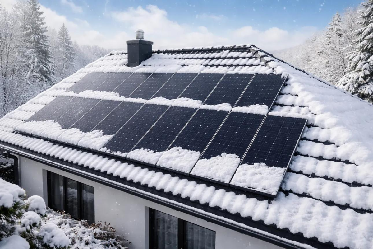
Ground snow load is the starting point for many code-based roof snow-load calculations. It varies with geographic location, elevation, climate, and the governing building code. Project teams should obtain the applicable site-specific value rather than use a generic regional average.
2.2 Panel tilt angle
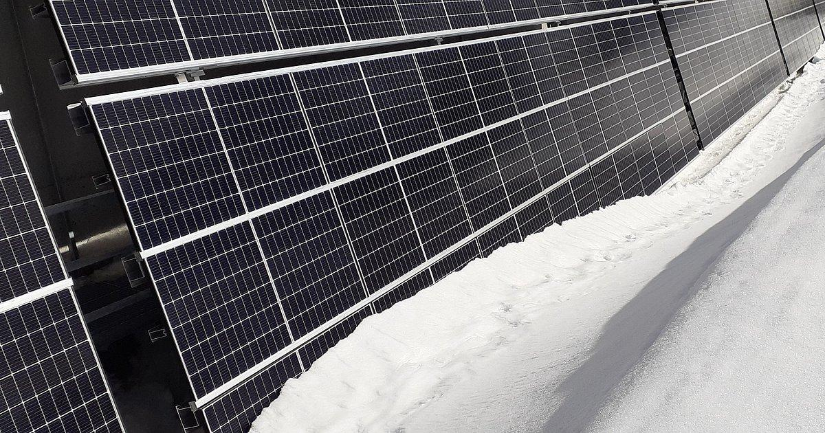
Tilt affects how snow accumulates and slides off the module surface. However, a steeper angle does not automatically mean that a lower design snow load can be used. The applicable code, snow retention, roof geometry, and possible sliding or drift conditions must be evaluated.
2.3 Elevation and exposure
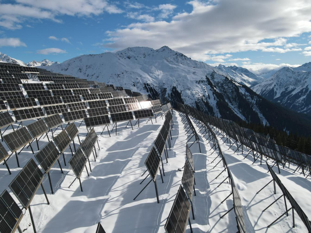
Higher elevations and local topography can significantly influence snow conditions. Wind exposure may redistribute snow, creating uneven accumulation across a solar array or around adjacent structures.
2.4 Structural layout and support spacing
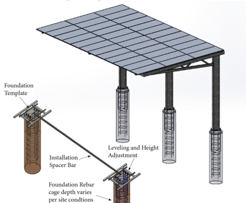
Rail span, purlin spacing, beam dimensions, column spacing, module arrangement, and connection details determine how snow loads are transferred through the mounting system. Longer spans generally require more careful deflection and strength checks.
Other factors include thermal conditions, roof obstructions, parapets, nearby buildings, snow sliding from upper surfaces, and the possibility of drifting or unbalanced snow.
3. How to Calculate Snow Load for a Solar Mounting System
The calculation method depends on the applicable design standard. Two widely referenced approaches are ASCE/SEI 7 in the United States and EN 1991-1-3 (Eurocode 1) in Europe.
These standards use different procedures and coefficients. They should not be combined into one universal formula.
3.1 Eurocode Method: Roof Snow Load
Under EN 1991-1-3, the characteristic snow load on a roof can be calculated using:
s = μᵢ × Cₑ × Cₜ × sₖ
Where:
s = Characteristic snow load on the roof (kN/m²).
μᵢ = Roof shape coefficient, accounting for roof geometry and snow distribution.
Cₑ = Exposure coefficient.
Cₜ = Thermal coefficient.
sₖ = Characteristic ground snow load for the site and relevant altitude.
The European Commission’s Joint Research Centre provides worked examples using this equation and explains how the roof shape coefficient adjusts ground snow load for roof geometry and snow accumulation conditions.
This equation is a characteristic-load calculation, not a complete verification of the mounting system’s design resistance. National Annex provisions, load combinations, unbalanced snow, and other applicable requirements must also be considered.
3.2 ASCE Method: Determine the Applicable Roof Snow Load
For projects governed by ASCE/SEI 7-22, the design process includes determining the site-specific ground snow load and calculating the applicable roof snow loads under Chapter 7.
Depending on the roof and project conditions, engineers may need to evaluate:
- Ground snow load
- Flat-roof snow load
- Sloped-roof snow load
- Exposure factor
- Thermal factor
- Snow importance factor
- Slope effects, unbalanced snow, drifting, and sliding snow.
The applicable equations and coefficients must be taken from the adopted standard and local building-code requirements. The Eurocode equation should not be substituted for the ASCE calculation procedure.
3.3 Worked example: a Eurocode snow-load calculation
Consider a hypothetical solar mounting project with the following assumed inputs:
| Parameter | Assumed value |
| Characteristic ground snow load | 1.00 kN/m² |
| Roof shape coefficient | 0.80 |
| Exposure coefficient | 1.00 |
| Thermal coefficient | 1.00 |
Using the Eurocode equation:
s = μᵢ × Cₑ × Cₜ × sₖ
s = 0.80 × 1.00 × 1.00 × 1.00
s = 0.80 kN/m²
The calculated characteristic roof snow load for this simplified example is 0.80 kN/m², equivalent to 800 N/m².
If the relevant uniformly loaded horizontal projected area is 100 m², the corresponding total characteristic snow load would be:
F = s × A
F = 0.80 × 100
F = 80 kN
This is approximately 8.15 metric tonnes-force.
This example illustrates the calculation method only. The assumed ground snow load and coefficients are not universal code values, and the result is not a certified mounting-system capacity. Actual PV geometry, the applicable National Annex, load distribution, and structural design checks may change the required design.
4. How to Convert Snow Pressure into Loads on Rails and Supports
After establishing the applicable design snow pressure, engineers must determine how the load is distributed across the PV modules, mounting rails, beams, posts, and foundations.
Step 1: Determine the Tributary Area
The tributary area is the portion of the loaded surface whose force is transferred to a particular structural member.
For a simplified uniformly loaded rail:
w = q × b
Where:
w = Distributed line load on the rail (kN/m).
q = Applicable design pressure (kN/m²).
b = Tributary width supported by the rail (m).
For example, if q = 0.80 kN/m² and the tributary width is 1.20 m:
w = 0.80 × 1.20
w = 0.96 kN/m
The rail’s actual load distribution depends on the mounting layout and support conditions.
Step 2: Check Rail Bending and Deflection
For an idealized simply supported beam carrying a uniformly distributed load:
Maximum bending moment:
M_max = wL² / 8
Maximum elastic deflection:
δ_max = 5wL⁴ / (384EI)
Where:
M_max = Maximum bending moment.
L = Span between supports.
E = Elastic modulus of the rail material.
I = Second moment of area of the rail section.
δ_max = Maximum elastic deflection.
These equations are useful for preliminary understanding, but real solar rails may have continuous spans, cantilevers, concentrated connection loads, and nonuniform loading.
Final design must use the correct structural model, material properties, section orientation, and code-required checks.
Step 3: Verify the entire load path
The assessment must extend beyond the rails to include:
- Module clamps and their connection to the rails.
- Rail splices and bracket fasteners.
- Purlins, beams, and columns.
- Roof attachments or ground-mount foundations.
- Local buckling, member stability, connection strength, and serviceability.
A rail that passes an isolated bending check does not automatically establish the capacity of the complete PV mounting system.
5. Snow Load Design Considerations for Different Solar Mounting Systems
5.1 Rooftop solar mounting systems
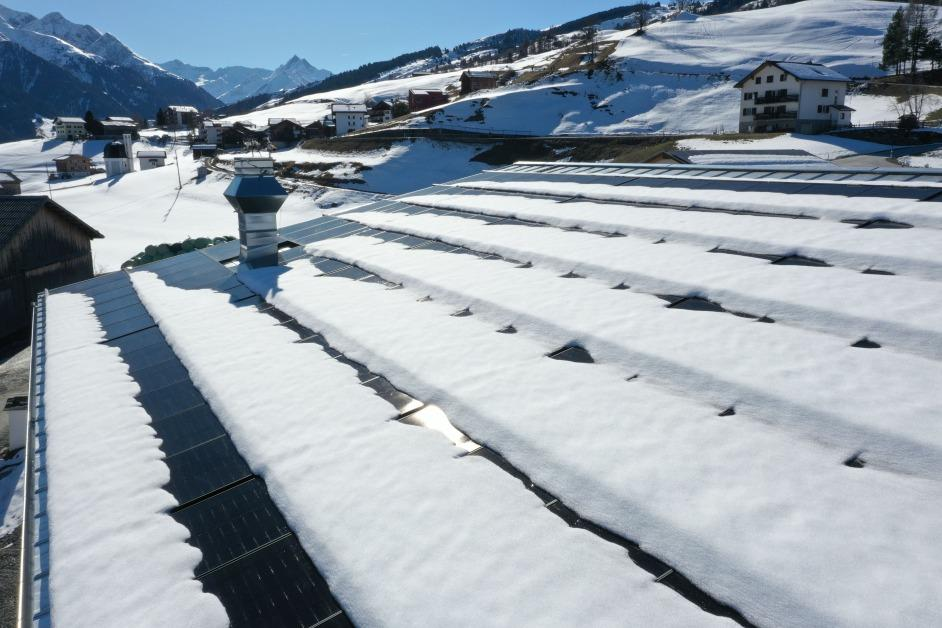
Rooftop PV systems must be checked against both the applicable PV-system loads and the capacity of the existing roof structure. Engineers should review roof framing, attachment locations, rail spans, panel tilt, snow sliding, and local snow accumulation.
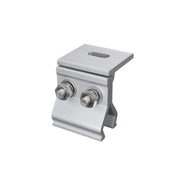
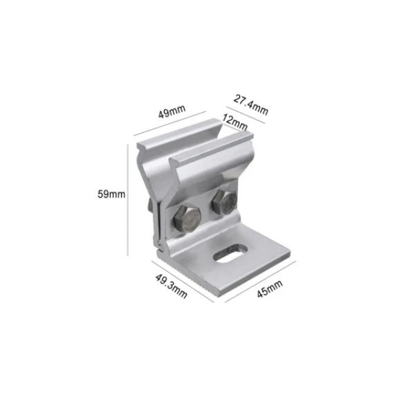
ALV offers rooftop mounting options for different roof configurations. Final suitability depends on the project-specific structural assessment.
5.2 Ground-mounted solar systems
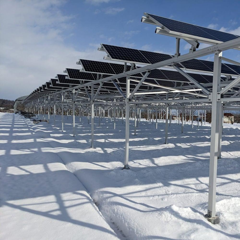
Ground-mounted arrays require checks of rails, support members, foundations, and the transfer of loads into the soil. Uneven snow accumulation, terrain, module arrangement, wind exposure, and foundation conditions may all affect the design.
ALV provides ground-mount solutions using aluminum and steel configurations selected according to project requirements.

5.3 Solar carport mounting systems
Carports combine PV modules with an elevated canopy structure. In addition to snow loads on the canopy, engineers must assess beams, columns, connections, foundation reactions, and load combinations involving wind and other applicable actions.
Because carport geometries and column layouts vary considerably, each design should be evaluated using its actual dimensions and site conditions.
Explore ALV’s rooftop, ground-mount, and carport solar mounting solutions.
6. Which Standards Should EPC Contractors Follow?
The correct standard depends on the project’s jurisdiction and the building code adopted by the local authority.
| Стандарт | Приложение |
| ASCE/SEI 7-22 | Structural loads and load combinations in projects governed by the relevant US building code. |
| EN 1991-1-3 | Snow actions on structures under the Eurocode framework, together with the applicable National Annex. |
| International Building Code (IBC) | Building-code provisions that reference ASCE 7 for determining snow loads, subject to the adopted edition and local amendments. |
ASCE 7-22 contains dedicated provisions for ground and roof snow loads, drifting, sliding snow, and related structural conditions. The IBC establishes requirements for documenting snow-load design information and references ASCE 7 for design snow loads.
Do not use generic snow-load ranges as engineering design values. A value appropriate for one city, elevation, risk category, or roof configuration may be unsuitable for another project. Confirm the governing code edition, local amendments, and site-specific parameters before sizing the mounting structure.
7. How to Select a Solar Mounting System for Heavy Snow Conditions
When evaluating a PV racking supplier, EPC contractors and project developers should consider more than the nominal load rating.
Use the following checklist during technical evaluation:
- Confirm the project-specific design snow load and governing code.
- Review module dimensions, orientation, tilt angle, and mounting layout.
- Verify rail span, support spacing, and structural member dimensions.
- Check clamps, fasteners, splices, and other connections.
- Evaluate the complete load path to the roof, foundations, or supporting structure.
- Assess unbalanced snow, drifting, sliding, and other relevant load cases.
- Verify material grades, section properties, corrosion protection, and design documentation.
- Confirm that the complete system meets the required strength, stability, and deflection criteria.
For cold-climate projects, request project-specific engineering documentation rather than relying solely on a general statement that a mounting system is suitable for snowy regions.
8. ALV Solar Mounting Systems for Demanding Environments
ALV supplies solar mounting solutions for rooftop, ground-mounted, and carport PV projects. Its product range includes aluminum mounting structures, steel ground-mount options, rails, clamps, and installation accessories.
For projects with significant snow loads, ALV can work with customers to review the mounting configuration and identify the technical information needed for project evaluation.
Relevant considerations include:
- Material selection: Aluminum and steel configurations can be evaluated according to structural requirements, corrosion conditions, and project economics.
- Mounting configuration: Rail spans, support spacing, module orientation, and connection details must match the project design.
- Project customization: Roof type, ground conditions, carport geometry, and local environmental loads influence the required configuration.
- Engineering coordination: Site-specific snow and wind data, module specifications, drawings, and applicable standards are essential for a reliable assessment.
Learn more about ALV Solar and its solar mounting system solutions.
9. Frequently Asked Questions
9.1 How much snow load should a solar mounting system support?
There is no single snow-load capacity suitable for every PV project. The required capacity depends on site-specific snow data, the governing code, mounting geometry, module layout, support spacing, and structural load combinations.
9.2 Does a higher solar panel tilt reduce snow load?
A higher tilt may encourage snow sliding under some conditions, but the reduction in design load cannot be assumed. Engineers must apply the relevant code provisions and consider snow retention, sliding hazards, and uneven accumulation.
9.3 What is the difference between ground snow load and roof snow load?
Ground snow load describes the snow loading parameter at the site used by the applicable design method. Roof snow load accounts for the effects of roof geometry, exposure, thermal conditions, and other code-defined factors. The two values are not necessarily equal.
9.4 Can aluminum solar mounting systems be used in heavy snow regions?
Aluminum mounting systems can be used where the selected sections, connections, spans, and overall structure are adequately designed for the required loads. Material choice alone does not establish structural capacity.
9.5 Do solar carports need separate snow-load calculations?
Solar carports require structural evaluation of the canopy, beams, columns, connections, and foundations under the applicable load cases. The calculation should reflect the actual carport geometry and site conditions.
9.6 Can I estimate snow load using local snowfall depth?
Snowfall depth alone is insufficient for a reliable structural calculation. Snow density, accumulated snow weight, geographic design criteria, drift conditions, and the applicable building code must also be considered.
9.7 What information should I provide to a mounting-system supplier?
Provide the project location, applicable design standard, required ground or roof snow load, module specifications, panel tilt and layout, structural drawings, support spacing, roof or foundation details, and any project-specific engineering requirements.
9.8 Does a mounting system’s snow-load rating guarantee the safety of the entire PV installation?
Not necessarily. The rating must be understood in the context of the tested or calculated configuration. Module capacity, connections, supporting structures, roof framing or foundations, and code-required load combinations must all be checked.
10. Conclusion
Accurate snow-load calculations are essential to selecting a reliable solar mounting system for projects in cold climates and high-altitude regions. The design process begins with site-specific snow data, applies the governing building-code method, and verifies the complete structural load path from the PV modules to the roof or foundations.
For EPC contractors, developers, and solar installers, working with a mounting-system supplier that understands project-specific engineering requirements can help reduce design uncertainty and improve procurement decisions.
Planning a rooftop, ground-mounted, or solar carport project? Contact ALV to discuss your mounting requirements and the technical information needed to evaluate a suitable solution.