

Solar Mounting System Grounding and Bonding: A Practical Guide(2026)

Last Updated: November 11th, 2026
مؤلف: Devi Huang | International Sales Team, ALV
ديفي هوانغ عضو في فريق المبيعات الدولية في شركة ALV، وهي شركة مصنعة لأنظمة تركيب الألواح الشمسية وقطاعات الألمنيوم. وهي تعمل مع مقاولي الهندسة والمشتريات والإنشاءات، والموزعين، ومطوري المشاريع في جميع أنحاء العالم، لمساعدة العملاء على اختيار حلول التركيب المناسبة بناءً على متطلبات المشروع، والمعايير المحلية، والميزانية.
Grounding and bonding are essential parts of a safe and reliable solar photovoltaic (PV) installation. Although solar panels and mounting structures are designed primarily to support modules under wind, snow, and other environmental loads, their electrical safety must also be considered during system design and installation.
A properly designed grounding and bonding system helps maintain electrical continuity between exposed conductive components, provides an appropriate fault-current path, and supports the operation of protective devices when an electrical fault occurs.
For EPC contractors, solar installers, project developers, and procurement teams, understanding these requirements is important when selecting PV mounting rails, module clamps, bonding components, and other mounting accessories.
In this practical guide, we explain the difference between grounding and bonding, how they apply to solar mounting systems, which components require attention, and how to avoid common installation mistakes.
1. What Are Grounding and Bonding in Solar Mounting Systems?
Grounding and bonding are related electrical safety measures, but they serve different purposes.
1.1 What Is Grounding?
Grounding refers to connecting designated parts of an electrical system to earth or to an established grounding reference, according to the applicable electrical design and code.
In a PV installation, grounding arrangements help provide a reference for electrical protection and may include a grounding electrode system, grounding electrode conductors, and equipment grounding conductors.
The exact configuration depends on the inverter topology, PV system design, applicable electrical code, and equipment manufacturer’s instructions.
1.2 What Is Bonding?
Bonding establishes electrical continuity between conductive components that must be electrically connected for safety.
In a solar mounting system, bonding may connect:
- Solar module frames to mounting rails.
- Adjacent modules through approved bonding hardware.
- Separate metallic mounting sections where required.
- Mounting structures to the designated equipment grounding conductor.
- Other exposed conductive equipment to the grounding and bonding network.
A mechanical connection does not automatically establish a reliable electrical bond. Approved bonding components and installation methods are therefore important.
1.3 Grounding vs. Bonding: What Is the Difference?
| Feature | Grounding | Bonding |
| Primary purpose | Establishes the required connection to earth or a grounding reference | Establishes electrical continuity between conductive parts |
| Typical components | Grounding electrodes and grounding conductors | Bonding clamps, bonding jumpers, and approved conductive connections |
| Application in PV systems | Supports the system’s grounding and protection arrangement | Helps maintain electrical continuity across modules, rails, and structural components |
| Key design consideration | Correct grounding configuration and conductor sizing | Approved bonding hardware, reliable contact, and installation compatibility |
Both functions must be considered in the overall electrical design. Bonding metal components together does not, by itself, replace the required grounding connections.
2. Why Are Grounding and Bonding Important for Solar Mounting Systems?
A PV mounting system contains multiple conductive components, including aluminum module frames, mounting rails, steel support structures, clamps, and fasteners. If an electrical fault energizes an exposed metal component, an inadequate bonding path may increase the risk of electric shock or prevent protective devices from operating as intended.
A properly engineered grounding and bonding arrangement helps address several key concerns.
2.1 Personnel Safety
Bonding exposed conductive parts helps reduce hazardous voltage differences between components that people may touch.
When a fault occurs, an appropriately designed equipment grounding path helps fault-detection and protective devices respond as intended.
2.2 Electrical Fault Protection
Grounding and bonding support the overall fault-protection strategy of a PV system.
They must be coordinated with inverter protection, overcurrent protection where applicable, ground-fault detection, and the equipment grounding conductor.
Grounding is not a substitute for other required electrical protection measures.
2.3 Long-Term System Reliability
Solar mounting systems operate outdoors and may experience moisture, temperature fluctuations, dust, salt exposure, and corrosion.
These conditions can affect electrical connections over time. Appropriate materials, compatible hardware, installation torque, and periodic inspections help maintain reliable connections.
2.4 Code Compliance and Project Acceptance
Electrical inspectors and project engineers may require documentation showing how the PV modules, mounting system, and associated equipment are bonded and grounded.
In the United States, relevant requirements include NFPA 70 (National Electrical Code), particularly Articles 250 and 690. Other markets may follow IEC-based standards or national electrical regulations.
Reference: U.S. Department of Energy — Solar Permitting Guidebook
3. Which Components of a Solar Mounting System Need Attention?
The exact grounding and bonding requirements depend on the system design, the listed equipment, and the applicable code. The following components commonly require evaluation.
3.1 Solar Panel Frames
Most framed PV modules have conductive metal frames. These frames must be connected to the equipment grounding network using an approved method where required.
Installers should verify that the selected bonding hardware is compatible with the module frame and mounting system.
Do not assume that ordinary module clamps automatically provide the required electrical bonding function.
3.2 Aluminum Mounting Rails
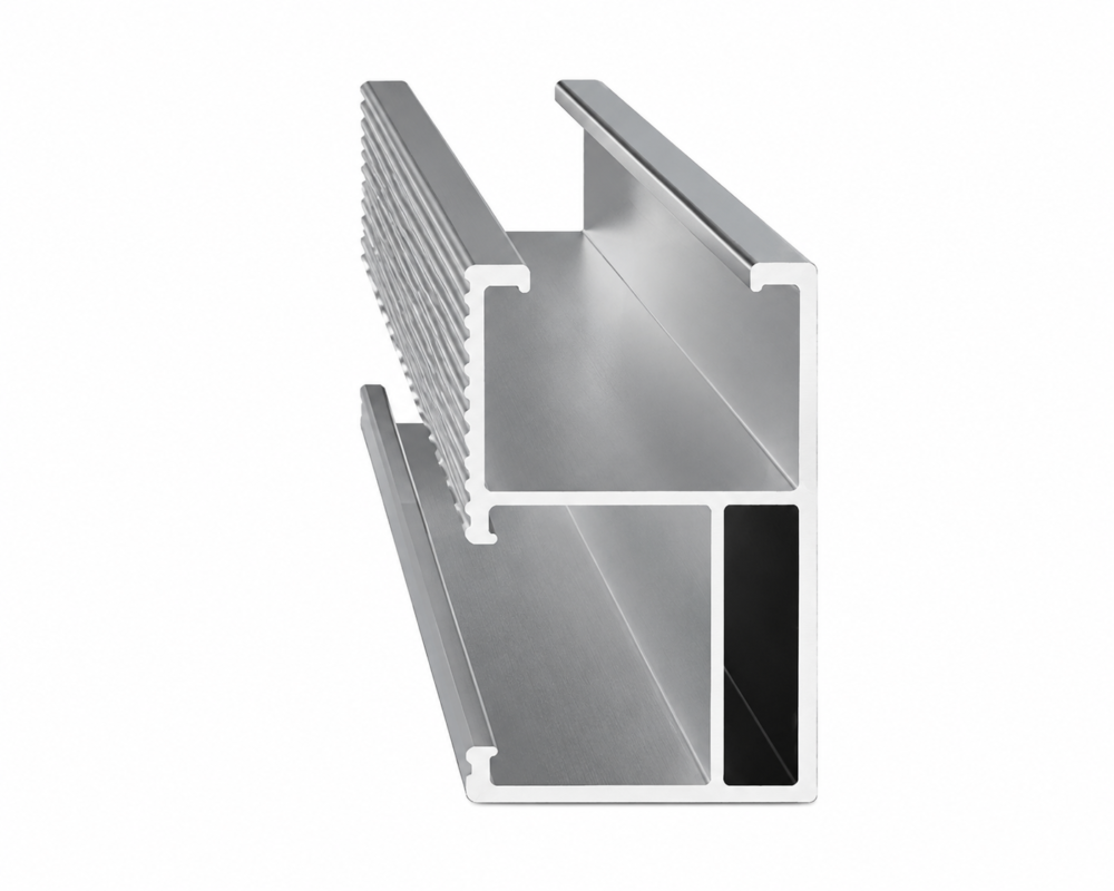
Aluminum rails support the modules and provide the mounting interface for clamps and other accessories.
Where the rails form part of the bonding path, their electrical continuity must be established using a method approved for the specific system.
Important considerations include:
- Rail profile and compatibility with bonding hardware.
- Rail splice design and electrical continuity between sections.
- Surface coatings and contact interfaces.
- Compatibility between aluminum rails and other metals.
- Installation torque and manufacturer instructions.
A rail may be mechanically secure while still failing to provide a reliable electrical connection. Structural performance and electrical bonding should therefore be evaluated separately.
3.3 Module Clamps and Bonding Clamps
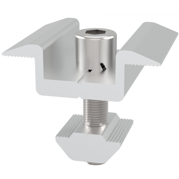
Standard module clamps secure the modules to the rails. Bonding clamps or other listed bonding devices are designed to establish the required electrical connection.
Depending on the system, a bonding device may use specially designed contact features to penetrate or displace a surface coating at a designated contact point.
The installer must use only the components and installation methods specified for the applicable mounting system and module combination.
3.4 Rail Splices and Structural Connections
Rail splices connect separate rail sections and may be important to the electrical continuity of the array.
However, not every splice connector is suitable for bonding.
If a splice is not identified or approved for the intended bonding function, an additional bonding jumper or another approved method may be necessary.
The same principle applies to connections between separate metallic structural sections.
3.5 Equipment Grounding Conductors
An equipment grounding conductor (EGC) provides the designated conductive path connecting equipment and exposed metal parts to the applicable grounding and protection system.
Its routing and sizing must follow the relevant electrical code and system design.
Under the U.S. NEC framework, Article 690 addresses PV-specific requirements, while Article 250 covers general grounding and bonding provisions.
Important: The structural mounting system should not be treated as the sole equipment grounding path unless the applicable system is specifically identified and approved for that function.
4. How Does Grounding and Bonding Work in a PV Mounting System?
A typical rooftop PV installation may use the following arrangement, provided that it is compatible with the approved system design.
- Module frame: The PV module is mechanically secured and electrically bonded using approved mounting hardware.
- Mounting rail: The bonding connection establishes electrical continuity between the module frame and the designated rail.
- Rail splice: Where necessary, an approved bonding connection maintains continuity between separate rail sections.
- Bonding jumper or designated connection: Required metallic sections are connected using the specified bonding method.
- Equipment grounding conductor: The array’s exposed conductive components are connected to the equipment grounding network.
- Grounding and protection system: The grounding arrangement connects to the relevant electrical system in accordance with the design, inverter requirements, and local code.
This sequence is a conceptual explanation, not a universal wiring diagram. The actual arrangement may differ between rooftop, ground-mounted, and solar carport installations.
5. Which Standards Apply to Solar Mounting System Grounding and Bonding?
There is no single international standard that covers every aspect of PV grounding, bonding, electrical protection, and mounting-system qualification. Applicable requirements depend on the installation location and system configuration.
The following documents are useful starting points.
5.1 NFPA 70: National Electrical Code (NEC)
For projects in the United States, NFPA 70 is a key reference for electrical installation requirements.
Relevant provisions include:
- Article 250: General grounding and bonding requirements.
- Article 690: Solar photovoltaic system requirements.
- Section 690.43: Equipment grounding and bonding of PV systems.
- Section 690.45: Sizing of equipment grounding conductors for PV source and output circuits.
- Section 690.47: Grounding electrode system requirements.
The adopted NEC edition and local amendments must be verified for each project. Designers should consult the complete, applicable edition rather than relying on excerpts from older editions.
Official resource: National Fire Protection Association
5.2 UL 2703: Mounting Systems, Mounting Devices, Clamping/Retention Devices, and Ground Lugs for Use with Flat-Plate Photovoltaic Modules and Panels
UL 2703 is particularly relevant to solar mounting manufacturers, installers, and EPC procurement teams in the North American market.
It addresses qualification of specified PV mounting and bonding equipment under its applicable scope.
When evaluating a mounting system, verify:
- Whether the specific system is listed or certified for the intended application.
- Which module types and mounting configurations are covered.
- Which bonding components and installation methods are included.
- Whether the proposed combination falls within the certification scope.
A certification associated with one rail, clamp, or module combination should not automatically be assumed to cover every possible configuration.
Official resource: UL Solutions
5.3 IEC 60364-7-712: Electrical Installations — Solar Photovoltaic (PV) Power Supply Systems
IEC 60364-7-712 addresses electrical installation requirements for PV power supply systems.
It is a useful reference when coordinating PV electrical design with the relevant IEC-based national installation rules.
The applicable edition and local adoption should be confirmed by the project’s electrical engineer.
Official resource: International Electrotechnical Commission
5.4 IEC 62548-1: Photovoltaic (PV) Arrays — Design Requirements
IEC 62548-1 provides design requirements for PV arrays within its defined scope.
It can help engineers coordinate array configuration and electrical design, including the requirements that influence safe installation.
The current applicable edition and any national modifications should be checked before specifying compliance.
Official resource: International Electrotechnical Commission
5.5 Solar ABCs: Photovoltaic System Grounding
The Solar America Board for Codes and Standards (Solar ABCs) published technical guidance on PV system grounding with support from the U.S. Department of Energy.
The resource explains grounding concepts, relevant electrical codes, and considerations for different PV system configurations.
Compliance note: Standards are not interchangeable. A mounting-system structural test, an electrical bonding qualification, and a complete PV installation’s code compliance are different matters. Project specifications should identify the exact requirements and applicable certification scope.
6. Common Grounding and Bonding Mistakes to Avoid
Even a well-designed mounting system can be installed incorrectly. EPC contractors and installation teams should pay attention to the following issues.
Mistake 1: Assuming Metal-to-Metal Contact Is Sufficient
Bolted metal components do not automatically provide a reliable electrical bond.
Oxide layers, coatings, contamination, corrosion, and unsuitable interfaces can affect electrical continuity.
Recommended practice: Use the designated bonding hardware and follow the manufacturer’s installation instructions.
Mistake 2: Using Unapproved Clamps or Fasteners
A conventional clamp may provide adequate mechanical retention without being qualified for the required electrical bonding function.
Recommended practice: Verify the intended use, compatibility, and approval of the specified clamps and bonding devices.
Mistake 3: Ignoring Rail Splices
A rail splice can connect two sections structurally without necessarily providing the required electrical continuity.
Recommended practice: Check whether the specified splice is approved for bonding. Add an approved bonding method where required.
Mistake 4: Mixing Incompatible Metals
Connections involving aluminum, copper, stainless steel, or galvanized steel require careful material selection.
Moisture and electrolytes can contribute to galvanic corrosion when dissimilar metals are improperly combined.
Recommended practice: Use compatible connectors and protective measures approved for the specific environment and material combination. Pay particular attention to coastal installations.
Mistake 5: Incorrect Installation Torque
Under-tightening can compromise a connection. Over-tightening can damage threads, clamps, or contact surfaces.
Recommended practice: Follow the specified torque values and installation procedure for each component.
Mistake 6: Failing to Inspect After Installation
A connection that initially appears correct may later deteriorate because of corrosion, mechanical damage, or maintenance activities.
Recommended practice: Include bonding connections in commissioning inspections and periodic maintenance according to the project requirements and manufacturer recommendations.
Mistake 7: Confusing Grounding With Lightning Protection
Grounding and bonding do not automatically provide a complete lightning protection system.
Projects with lightning protection requirements need coordinated engineering that considers the PV array, building protection system, surge protective devices, and applicable standards.
Recommended practice: Have the electrical engineer determine how the PV installation interfaces with the building’s lightning protection and grounding systems.
7. How to Inspect Grounding and Bonding Before Commissioning
A practical inspection process helps reduce installation errors and improves documentation quality.
| Inspection item | What to verify |
| Module frames | Correct bonding method and compatibility with the mounting system |
| Aluminum rails | Approved bonding arrangement and continuity between required sections |
| Rail splices | Bonding qualification or additional connection where required |
| Clamps and fasteners | Correct component type, installation position, and specified torque |
| Conductors | Correct type, sizing, routing, and mechanical protection |
| Material interfaces | Suitability for outdoor and corrosive environments |
| Grounding connections | Compliance with the approved electrical design |
| Documentation | Manufacturer instructions, applicable certifications, and inspection records |
Electrical continuity testing should be performed using an appropriate instrument and procedure. A continuity reading alone does not establish complete code compliance or prove that every fault condition will be safely cleared.
The commissioning team should also verify the operation of the required protective devices and complete the electrical tests specified for the project.
8. How Should EPC Contractors Select a Solar Mounting System?
Grounding and bonding should be considered during mounting-system selection, not added as an afterthought during installation.
EPC contractors and procurement teams should evaluate the following factors.
8.1 Structural and Electrical Compatibility
The mounting system must meet the project’s structural design requirements while also supporting the specified electrical bonding arrangement.
Check the compatibility of the module frames, rails, clamps, splices, bonding hardware, and grounding conductors.
8.2 Environmental Conditions
Consider temperature changes, rainfall, humidity, salt exposure, and other site-specific environmental conditions.
For coastal or industrial sites, material compatibility and corrosion resistance are particularly important.
8.3 Installation Efficiency
A well-coordinated mounting design can reduce unnecessary components, simplify assembly, and make inspection easier.
However, installation efficiency must not come at the expense of electrical safety or compliance.
8.4 Certification and Documentation
Request relevant product documentation before procurement, including:
- Mounting-system installation instructions.
- Applicable structural and electrical certifications.
- Module and clamp compatibility information.
- Bonding component specifications.
- Material and surface-finish information.
- Inspection and maintenance recommendations.
Confirm that documentation applies to the actual product configuration being supplied.
8.5 Project-Specific Engineering
Rooftop, ground-mounted, and carport installations may use different structural configurations and environmental protection strategies.
For this reason, mounting-system selection should account for the project drawings, module specifications, site conditions, and applicable electrical requirements.
9. Frequently Asked Questions
Q1. What is the difference between grounding and bonding in a solar mounting system?
Grounding establishes the required connection to earth or an electrical grounding reference. Bonding connects conductive components to maintain electrical continuity and reduce hazardous voltage differences. Both must be addressed in the system’s electrical design.
Q2. Do aluminum solar mounting rails need to be grounded?
Where aluminum rails are exposed conductive parts within the scope of applicable electrical grounding requirements, they must be incorporated into the required grounding and bonding arrangement. The exact method depends on the mounting system, approved hardware, and applicable code.
Q3. Can solar panels be grounded through their mounting clamps?
Yes, if the specified mounting and bonding hardware is identified or approved for that function and is installed in accordance with its instructions. Ordinary mechanical clamps should not automatically be assumed to provide electrical bonding.
Q4. Do rail splices need bonding jumpers?
Not always. A rail splice may be suitable for electrical bonding if it is specifically qualified for that purpose within the mounting system. If electrical continuity is not established by the approved splice, another approved bonding method may be required.
Q5. Does UL 2703 cover solar mounting system grounding and bonding?
UL 2703 addresses specified PV mounting, clamping, retention, and grounding equipment within its scope. The applicable listing or certification must be checked for the exact mounting system, components, modules, and installation configuration.
Q6. How often should solar mounting system bonding connections be inspected?
Inspection frequency should follow the applicable code, project maintenance plan, environmental conditions, and manufacturer instructions. Additional attention may be appropriate for systems exposed to coastal salt, severe weather, or corrosive industrial environments.
Q7. Does grounding a solar mounting system provide lightning protection?
No. Grounding and bonding are important electrical safety measures, but they do not automatically constitute a complete lightning protection system. Lightning protection and surge protection must be addressed through coordinated project engineering.
Q8. What should EPC contractors check before purchasing a solar mounting system?
EPC contractors should confirm structural suitability, module and rail compatibility, bonding hardware, relevant certifications, installation instructions, environmental conditions, and project-specific electrical requirements.
10. How ALV Supports Solar Mounting System Projects
ALV specializes in solar mounting systems and aluminum profiles, supporting project requirements across rooftop, ground-mounted, and solar carport applications.
Selecting a suitable mounting system involves more than choosing a rail or clamp. Structural performance, material compatibility, installation efficiency, environmental conditions, and electrical bonding requirements should be evaluated together.
When assessing a mounting solution for your project, consider:
- Application suitability: Rooftop, ground-mounted, or carport configurations.
- Material selection: Aluminum or steel components according to structural, environmental, and project requirements.
- Component compatibility: Rails, clamps, brackets, and accessories designed for the intended assembly.
- Installation requirements: Clear component specifications and installation documentation.
- Project coordination: Review of drawings, module information, and site-specific requirements before finalizing the mounting configuration.
Electrical grounding and bonding compliance must be established for the actual system configuration. Buyers should confirm the relevant approvals and documentation rather than assume that all mounting products provide the same electrical functions.
If you are planning a PV project, contact ALV to discuss your mounting-system requirements and identify the information needed for a project-specific solution.
Explore ALV: https://alv-solar.com/
Contact: sales@xmalv.com