

Solar Mounting System Load Calculation: A Practical Guide for EPCs(2026)

Last Updated: November 2nd, 2026
Author: Devi Huang | International Sales Team, ALV (E-mail address:sales@xmalv.com)
Devi Huang is part of the international sales team at ALV, a manufacturer of solar mounting systems and aluminum profiles. She works with EPC contractors, distributors, and project developers worldwide, helping customers choose the right mounting solutions based on project requirements, local standards, and budget.
Solar mounting system load calculation is a critical step in designing a safe, durable, and cost-effective photovoltaic (PV) installation. For engineering, procurement, and construction (EPC) companies, understanding how wind, snow, dead loads, and other site-specific forces affect a mounting structure helps prevent structural failures, reduce unnecessary material costs, and support project approval.
A solar mounting system must do more than hold PV modules in place. It must transfer the forces acting on the modules through rails, clamps, brackets, posts, and foundations into the supporting roof or ground structure.
The required design depends on the project location, building geometry, mounting configuration, local building codes, and properties of the supporting structure. There is no single wind pressure or snow load that applies to every solar installation.
This guide explains the essential calculation process, the engineering standards EPCs should consider, and the information required to develop a project-specific mounting solution.
1. What Is a Solar Mounting System Load Calculation?
A solar mounting system load calculation determines the forces that a PV array and its supporting structure must safely resist throughout their intended service life.
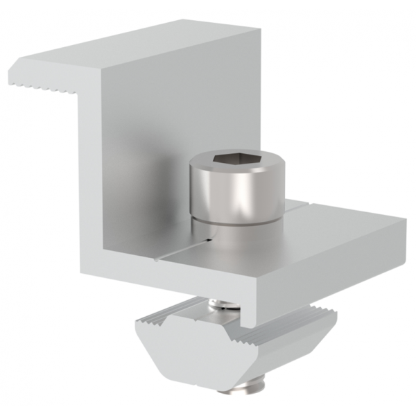
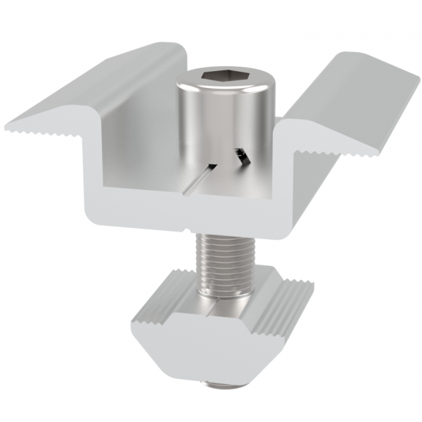
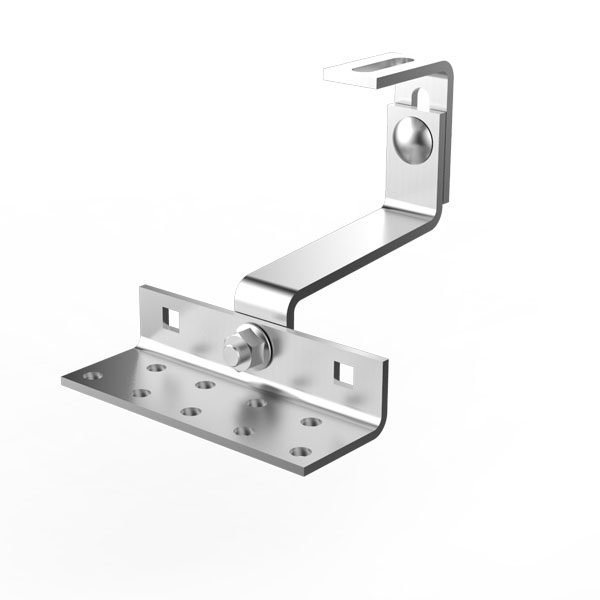
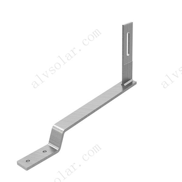
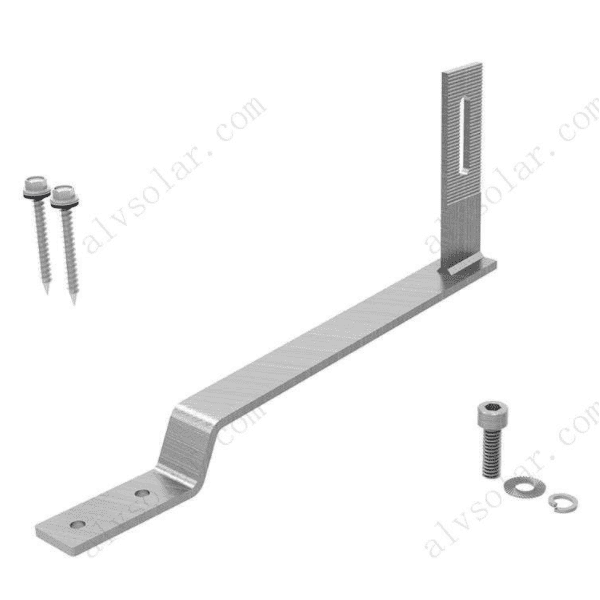
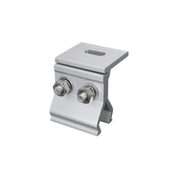
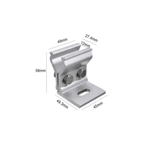
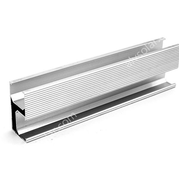
These calculations help engineers establish the required strength and stability of mounting rails, mid clamps, end clamps, roof attachments, posts, bracing, bolts, and foundations.
According to the American Society of Civil Engineers (ASCE), ASCE/SEI 7 addresses design loads and associated criteria for buildings and other structures, including wind, snow, dead loads, and load combinations. The applicable edition and local amendments must be confirmed for each project.
A complete PV mounting system assessment should consider three interconnected questions:
- What loads act on the PV array? Wind pressure, wind uplift, snow, module weight, and other applicable actions.
- How are those loads transferred? Through clamps, rails, brackets, structural members, connections, and foundations.
- Can the complete structure resist the resulting forces? The modules, mounting components, supporting structure, and connections must each satisfy the applicable design requirements.
A component that passes an isolated strength check does not automatically make the entire mounting system safe. The complete load path must be verified.
2. The Main Loads Acting on Solar Mounting Systems
2.1 Dead Load
Dead load is the permanent weight of the installed system. Depending on the design scope, it can include:
- PV modules
- Aluminum or steel mounting rails
- Mid clamps and end clamps
- Roof brackets or attachment assemblies
- Ballast blocks in ballasted systems
- Permanent cables, trays, and other supported equipment where applicable
For a preliminary calculation, the average dead-load pressure can be expressed as:
qD = WD / A
Where:
qD = average dead-load pressure, in kN/m²
WD = total supported dead weight, in kN
A = reference area, in m²
However, average pressure alone is not sufficient for structural verification. Rail reactions and attachment forces can concentrate the load on a small number of roof purlins, rafters, or other structural members.
EPCs should verify both the total additional roof load and the local forces at each attachment point. A roof should not be assumed suitable simply because the average PV system weight appears small.
2.2 Wind Load
Wind load is often one of the most important design considerations for solar mounting systems, particularly in coastal regions, exposed sites, elevated installations, and projects subject to severe storms.
Wind can create several types of force:
- Wind pressure: A force pushing against a surface.
- Wind uplift: A force pulling PV modules and their supporting structure away from the roof or ground.
- Overturning moment: A rotational effect that can increase tension in some connections and compression in others.
- Lateral force: A horizontal force acting on posts, bracing, rails, and foundations.
The actual pressure distribution depends on wind speed, terrain exposure, building height and geometry, array location, module tilt, edge clearances, and mounting configuration.
For rooftop systems, roof edges and corners can experience different wind effects from central roof zones. Ground-mounted arrays and carports also require consideration of airflow around and beneath the modules.
The U.S. Department of Energy identifies wind as a major cause of PV system damage and emphasizes the need to consider structural design and site-specific weather risks.
2.3 Snow Load
Snow load is the force imposed by accumulated snow on the PV modules and supporting structure.
It is particularly important for projects in cold climates, high-altitude locations, and regions where heavy snowfall or drifting may occur.
Engineers should evaluate:
- Ground snow load and the applicable conversion to roof or PV-system design snow load
- Roof slope and module tilt
- Snow accumulation and drift patterns
- Uneven snow distribution
- Local roof geometry and adjacent obstructions
- Applicable load combinations and local code requirement
Snow can accumulate unevenly around roof steps, parapets, nearby structures, and changes in array height. A uniform snow-pressure assumption may therefore be insufficient for some installations.
NREL’s PV system operations guidance also explains that array geometry and clearance affect snow accumulation and shedding. A low module tilt should not be assumed to eliminate snow loading.
2.4 Other Loads and Design Conditions
Depending on the project, the engineer may also need to evaluate:
- Roof live loads and maintenance access
- Rainwater accumulation and ponding where relevant
- Seismic actions
- Thermal expansion and contraction
- Installation and temporary construction loads
- Local corrosion exposure and material degradation
- Fatigue or repeated loading where applicable
Not every load applies to every project. The governing code, structural system, and site conditions determine the required design cases.
3. Which Standards Should EPCs Use?
The correct standard depends on the project country, permitting authority, structural material, and mounting configuration. EPCs should confirm the governing code before establishing design loads or requesting final structural calculations.
| Standard or reference | Typical role in PV mounting design |
| ASCE/SEI 7 | Establishes design loads, including wind, snow, and load combinations, for applicable U.S. projects. |
| International Building Code (IBC) | Provides building-code requirements for structural design and rooftop PV installations where adopted. |
| Eurocodes, including EN 1991 | Address actions on structures, including wind and snow, under the applicable national provisions. |
| Local building codes | Define jurisdiction-specific design criteria, maps, amendments, and approval requirements. |
| Applicable PV mounting system standards | Address relevant mounting-system safety, testing, listing, or performance requirements. |
For U.S. projects, the IBC provisions for rooftop PV systems address wind resistance and refer to applicable component-and-cladding wind loads. See the International Code Council’s IBC provisions. This is a reference to a specific edition, not a claim that the 2015 edition governs every current project.
ASCE/SEI 7-22 is an important reference for projects adopting that edition, but the latest published edition is not automatically the legally applicable edition in every jurisdiction.
For international projects, EPCs should also confirm the locally adopted editions of the Eurocodes or other national standards and any applicable national annexes.
Important: A mounting system’s product certification or test report does not replace project-specific structural calculations. Likewise, a general wind-speed value cannot be converted into a final mounting-system design load without the required engineering parameters.
4. How to Calculate Wind Load on a Solar Mounting System
Wind-load calculation should begin with the governing design standard, not with a guessed pressure value.
Step 1: Determine the design wind speed
Collect the basic wind speed or other prescribed wind-speed parameter required by the applicable code.
The input must be appropriate for the project’s location, risk category, reference averaging time, and code edition. Do not mix wind-speed definitions from different standards without a valid conversion method.
Step 2: Establish site and structure parameters
Depending on the standard, the engineer may need:
- Building or mounting-system height
- Terrain exposure and surrounding obstructions
- Topographic effects
- Roof geometry and roof-zone location
- PV array tilt, dimensions, and distance from the roof
- Module arrangement, gaps, and edge distances
- Ground-mounted or carport geometry
These parameters influence the pressure coefficients and force distribution used in the design.
Step 3: Determine the Applicable Wind Pressure
A simplified physical relationship between wind speed and dynamic pressure is:
q = ½ρV²
Where:
q = dynamic pressure, in Pa
ρ = air density, in kg/m³
V = wind speed, in m/s
This equation illustrates why wind speed matters: pressure increases approximately with the square of wind speed.
However, dynamic pressure is not the final design pressure on a PV mounting system. Code-based calculations may require exposure, height, gust, directionality, topographic, and aerodynamic factors. The relevant external and internal pressure coefficients, or other prescribed force coefficients, must be applied according to the selected standard.
Step 4: Calculate the Force on the Relevant Area
Once the applicable design pressure has been established, a simplified force relationship is:
F = pA
Where:
F = force, in N
p = applicable net design pressure, in Pa
A = corresponding loaded area, in m²
The pressure and area must be consistent with the selected code method. A module-level effective wind area, an entire array area, and a tributary area for a rail support are not automatically interchangeable.
For a complete design, engineers must distinguish between downward pressure and uplift and calculate the resulting forces and moments at the relevant structural components.
Step 5: Transfer the Forces Through the Mounting Structure
The engineer determines the load path from the PV modules to the supporting structure.
PV modules → Mid clamps and end clamps → Mounting rails and brackets → Roof structure, posts, and foundations
Each connection and structural element must be checked for the relevant failure modes. For rooftop systems, the roof deck, purlins, rafters, fasteners, and local substrate condition may govern the design even if the mounting rail itself has adequate strength.
For ground-mounted systems and carports, checks may extend to post buckling, bracing, base plates, anchor bolts, foundation resistance, and soil capacity.
5. How to Calculate Snow Load on a Solar Mounting System
Snow-load calculations should use the snow-load provisions of the governing code rather than a generic snow-pressure estimate.
Step 1: Establish the prescribed snow-load input
Depending on the code, the engineer may need ground snow load, roof snow load, snow importance factors, thermal factors, exposure factors, and other prescribed parameters.
Ground snow load and the final load acting on a PV array are not necessarily equal. The conversion depends on the governing standard and the structure’s geometry.
Step 2: Evaluate the mounting configuration
Consider whether the installation is:
- Flush-mounted on a pitched roof
- Elevated above a flat or low-slope roof
- Installed on a ground-mounted fixed-tilt structure
- Installed on a solar carport
- Adjacent to parapets, higher roofs, or other obstructions that may cause drifting
The array geometry can change snow accumulation and shedding patterns. A low tilt angle should not be treated as proof that snow will slide off.
Step 3: Determine the Design Snow Pressure
For illustration, suppose a hypothetical project has a verified uniform design snow pressure of 0.80 kN/m² acting over a horizontal projected area of 20 m².
The total vertical snow force is:
Fs = ps × Ah
Fs = 0.80 × 20 = 16 kN
This is an illustrative calculation only. The 0.80 kN/m² pressure is an assumed input, not a value prescribed for any location by a building code. The appropriate reference area and snow distribution must follow the governing standard.
The total force is then distributed through the PV modules and mounting structure based on their actual geometry, support locations, stiffness, and structural model.
Step 4: Check the governing combinations
Snow should not be checked in isolation. Engineers must evaluate the load combinations required by the applicable standard, including the relevant dead, snow, wind, and other loads.
The governing combination may differ between a module, a rail, a connection, a column, and a foundation. The most demanding case for one component may not govern another.
6. Worked Example: Preliminary Load Transfer for a Rooftop PV Array
Consider a hypothetical rooftop project with the following inputs.
| Parameter | Assumed value |
| Number of PV modules | 20 |
| Module dimensions | 2.2 m × 1.1 m |
| Total module face area | 48.4 m² |
| Average module mass | 28 kg |
| Mounting system mass | 300 kg |
| Illustrative uniform snow pressure | 0.80 kN/m² |
| Illustrative net wind pressure | 1.00 kN/m² |
These inputs are used only to demonstrate preliminary arithmetic. The wind and snow pressures are assumptions, not code-confirmed design values, and the module dimensions do not establish the correct code-defined wind area or horizontal snow-loaded area.
A. Estimate the Module Dead Load
Total module mass:
mPV = 20 × 28 = 560 kg
Using gravitational acceleration of approximately 9.81 m/s²:
WPV = (560 × 9.81) / 1000 = 5.49 kN
The mounting system’s estimated weight is:
Wmount = (300 × 9.81) / 1000 = 2.94 kN
Therefore, the estimated combined dead load of modules and mounting system is:
WD = 5.49 + 2.94 = 8.43 kN
This estimate excludes any other permanent loads not listed in the assumptions.
B. Estimate the Illustrative Snow Force
If, purely for demonstration, the assumed snow pressure acts uniformly over the 48.4 m² module face area:
Fs = 0.80 × 48.4 = 38.72 kN
The real calculation must use the area and pressure definition required by the governing code. In particular, a code-defined snow load based on horizontal projection must not be applied to module face area without checking the geometry and prescribed method.
C. Estimate the Illustrative Wind Force
If a hypothetical net wind pressure of 1.00 kN/m² acts uniformly on the same 48.4 m² reference area:
Fw = 1.00 × 48.4 = 48.4 kN
This represents a simplified force estimate only. A real wind calculation must account for the relevant pressure distribution, wind direction, effective wind area, and structural load path.
D. What does this example tell an EPC?
The calculations show how quickly total forces can become substantial even on a relatively small array. They do not establish that the assumed mounting structure is safe or unsafe.
Before finalizing a design, the engineering team must verify:
- The applicable wind and snow inputs for the project location
- The correct loaded area and pressure coefficients
- The spacing and tributary areas of rails and brackets
- Rail bending, shear, and deflection
- Clamp, bolt, and attachment capacity
- Roof-member, post, and foundation capacity
- Governing load combinations and applicable resistance factors
The final design should be based on verified project data and the appropriate structural analysis, not on these illustrative totals alone.
7. Load Calculation Differences: Rooftop, Ground-Mounted, and Carport Systems
Although these systems use similar structural principles, their load paths and critical design checks can differ significantly.
Rooftop solar mounting systems
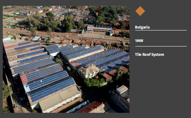
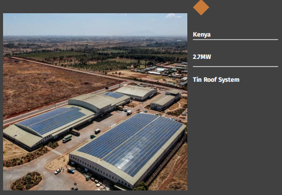
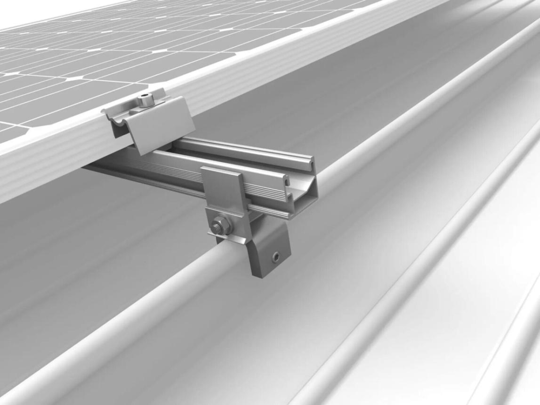
The existing roof structure is part of the load path. Engineers should assess roof attachment capacity, purlins or rafters, local roof-deck strength, waterproofing details, and wind uplift. For ballasted systems, ballast weight and roof reserve capacity also need evaluation.
Ground-mounted solar mounting systems
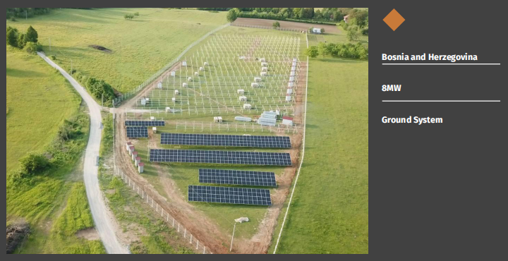
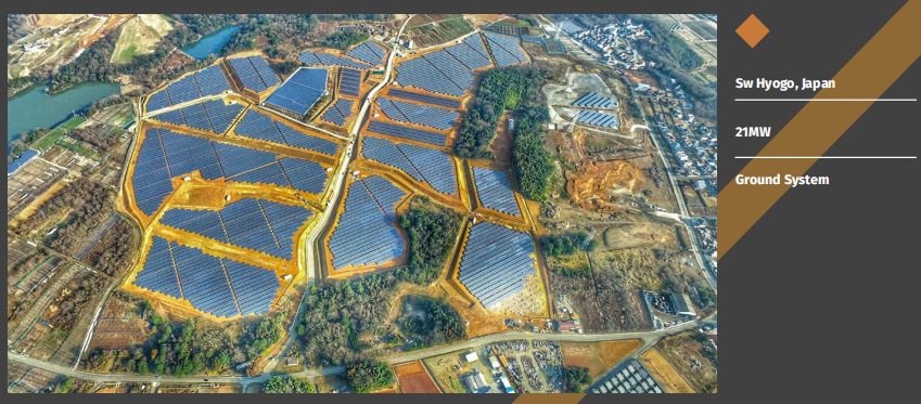
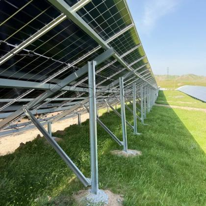
The design typically includes rails, support beams, columns, bracing, connections, foundations, and soil. Wind-induced overturning, post buckling, foundation uplift, lateral soil resistance, and differential settlement can be important checks.
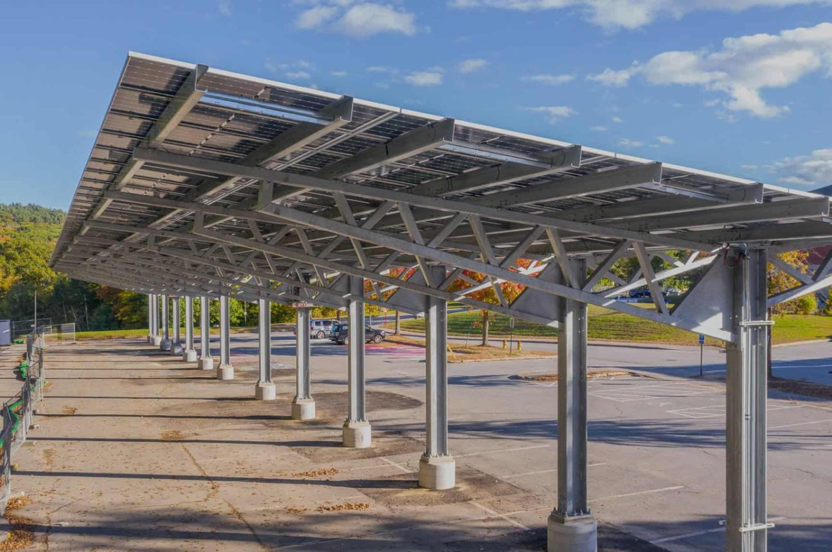
Solar carport mounting systems
Elevated canopies require attention to wind pressure and uplift, overturning, lateral stability, column and bracing forces, connection design, and foundation capacity. Clearance height, canopy geometry, and the wind exposure of the site can materially affect the design.
For all three configurations, the mounting design should be coordinated with the module manufacturer’s allowable loads, the applicable structural requirements, and the actual site conditions.
8. Common Mistakes in Solar Mounting System Load Calculation
Avoiding the following mistakes helps EPCs reduce redesign, procurement delays, and installation risks.
1. Using wind speed as if it were wind pressure. Wind speed must be interpreted using the governing standard’s definitions and calculation method. A basic wind speed alone does not establish the net pressure on a module.
2. Applying one pressure to the entire project. Roof corners, roof edges, roof centers, and different array positions may experience different wind effects. Ground arrays and carports have their own aerodynamic conditions.
3. Ignoring the complete load path. Checking only the rail’s strength overlooks clamps, fasteners, roof attachments, structural members, posts, and foundations.
4. Assuming the roof can support the array because the average weight is low. Concentrated reactions can govern the capacity of individual roof members. Existing roof condition and remaining structural capacity must be assessed.
5. Using generic snow-load values. Snow conditions, drift patterns, roof geometry, and code requirements vary by location. Unverified values should never be presented as code-mandated design loads.
6. Selecting a mounting structure before confirming the site inputs. A preliminary product selection should not be treated as a final engineering design. Changes in array tilt, span, support spacing, or module layout may affect structural performance and material requirements.
7. Treating certification as a substitute for project engineering. Product test reports and certifications can support system qualification, but they do not establish the suitability of every possible configuration, roof, soil condition, or project location.
9. EPC Checklist: Information Required Before Finalizing a Mounting Design
EPCs can speed up technical evaluation by providing a complete project information package before requesting a final mounting-system proposal.
Project readiness checklist
- Project location
Country, city, site coordinates, and applicable building code.
- Structural design criteria
Basic wind speed, exposure, snow load, risk category, seismic criteria, and required load combinations.
- PV module specifications
Manufacturer, model, dimensions, mass, frame details, and allowable mechanical loads.
- Array layout
Module quantity, portrait or landscape orientation, row spacing, tilt angle, spans, and support locations.
- Roof or foundation details
Roof type and drawings, purlin spacing, structural-member details, soil report, or foundation criteria as applicable.
- Project-specific conditions
Coastal corrosion exposure, topography, adjacent buildings, roof-edge zones, clearance height, and drainage considerations.
- Engineering deliverables
Required calculations, structural drawings, connection details, material specifications, and certification requirements.
Providing these details early helps the mounting-system supplier and EPC identify missing inputs before finalizing the structure, reducing avoidable design revisions.
10. How Proper Load Calculation Helps Reduce Project Costs
Structural safety and cost efficiency are not competing goals when a mounting system is properly engineered.
A project-specific calculation can help EPCs:
- Optimize material quantities: Select appropriate rail spans, support spacing, and structural sections without unnecessary overdesign.
- Reduce installation uncertainty: Identify attachment requirements and structural constraints before materials arrive on site.
- Improve procurement accuracy: Establish quantities, specifications, and connection requirements from a coordinated design.
- Support technical approvals: Provide documented calculations and drawings for review by the relevant engineer or authority.
- Reduce lifecycle risk: Address site-specific wind, snow, corrosion, and structural conditions before installation.
The goal is not simply to minimize aluminum or steel consumption. It is to achieve a compliant, buildable design with an appropriate balance of structural performance, installation efficiency, and total project cost.
11. Frequently Asked Questions
1. What loads should be considered when designing a solar mounting system?
The main loads typically include dead load, wind pressure and uplift, snow load where applicable, and roof live or maintenance loads. Depending on the project, engineers may also need to consider seismic actions, rainwater accumulation, thermal effects, and construction loads under the governing code.
2. How do you calculate wind load on solar panels?
The engineer determines the required wind-speed input under the applicable standard, evaluates site exposure and array geometry, obtains the relevant pressure or force coefficients, and calculates the forces on the PV modules and supporting structure. The resulting loads must then be transferred through the mounting components and checked against their design capacities.
3. Does a higher wind speed always require a stronger mounting system?
Higher design wind speeds generally increase wind-related forces, but the required mounting configuration also depends on array geometry, exposure, attachment locations, structural spans, and the applicable code. The final design should be based on the calculated component forces rather than wind speed alone.
4. How does snow load affect solar mounting system design?
Snow adds downward force to the modules, rails, and supporting structure. Uneven accumulation and drifting may create additional local effects. Engineers must evaluate the snow conditions and load combinations prescribed by the applicable code and verify the capacity of the complete structural system.
5. Can the same mounting system be used in different countries?
A mounting-system configuration may be suitable for multiple markets, but its structural suitability must be verified against each project’s local design requirements. Wind and snow criteria, structural materials, building codes, attachment details, and approval requirements can differ between countries and jurisdictions.
6. Is aluminum suitable for high-wind solar mounting systems?
Aluminum can be used in properly engineered PV mounting systems, including projects in exposed environments. Suitability depends on the alloy, temper, section geometry, connection design, corrosion environment, and calculated structural demand. Material selection alone does not establish wind-load capacity.
7. What information should EPCs provide to obtain a mounting-system quotation?
EPCs should provide the project location, module datasheet, preliminary array layout, roof or foundation details, local wind and snow design criteria, and applicable certification requirements. Drawings and installation constraints help the supplier evaluate the appropriate mounting configuration and identify any missing information.
8. Does a certified mounting system eliminate the need for structural calculations?
No. Certification or testing demonstrates performance within a defined scope and set of conditions. Project-specific calculations may still be necessary to verify the selected configuration, support spacing, attachments, supporting structure, and foundations under the governing design criteria.
12. How ALV Solar Supports EPC Mounting-System Projects
ALV Solar manufactures photovoltaic mounting systems and aluminum profiles for a range of solar applications, including rooftop, ground-mounted, and solar carport projects.
For EPCs developing a new project, selecting the mounting structure should go hand in hand with confirming the design conditions and installation requirements.
ALV can work with EPCs to evaluate the appropriate mounting-system configuration based on the project information provided, including:
- Rooftop mounting systems: Solutions for compatible metal-roof profiles and other roof configurations, subject to the selected attachment system and project requirements.
- Ground-mounted systems: Aluminum or galvanized-steel structural options, depending on project scale, environmental exposure, and engineering requirements.
- Solar carports: Mounting-system solutions coordinated with the proposed canopy layout, clearance, and structural design requirements.
- Aluminum profiles and mounting rails: Profile options for suitable applications, with customization assessed against drawings, dimensions, material specifications, and surface-finish requirements.
For a project-specific assessment, EPCs should share the site location, module datasheet, preliminary layout, applicable wind and snow criteria, and relevant roof or foundation drawings.
Planning a solar project? Contact ALV Solar to discuss your mounting-system requirements and provide the technical inputs needed for a project-specific proposal.