

Bifacial Solar Panel Mounting: 7 Best Practices for Higher Yield

Bifacial modules promise 5% to 20% more energy from the same panel area, but that extra output never arrives on its own. It depends almost entirely on how the array is mounted. Bifacial solar panel mounting has to do two jobs at once: hold the modules safely for 25 years, and leave the back of every panel open enough to collect reflected light. Get the structure right and the gain is real; get it wrong and you have paid a bifacial premium for monofacial performance.
This guide covers the seven decisions that matter most — rear-side clearance, mounting height, tilt, row spacing, rail layout, cabling and structural verification — and shows how each one changes the numbers on a real project.
Why bifacial solar panel mounting is different
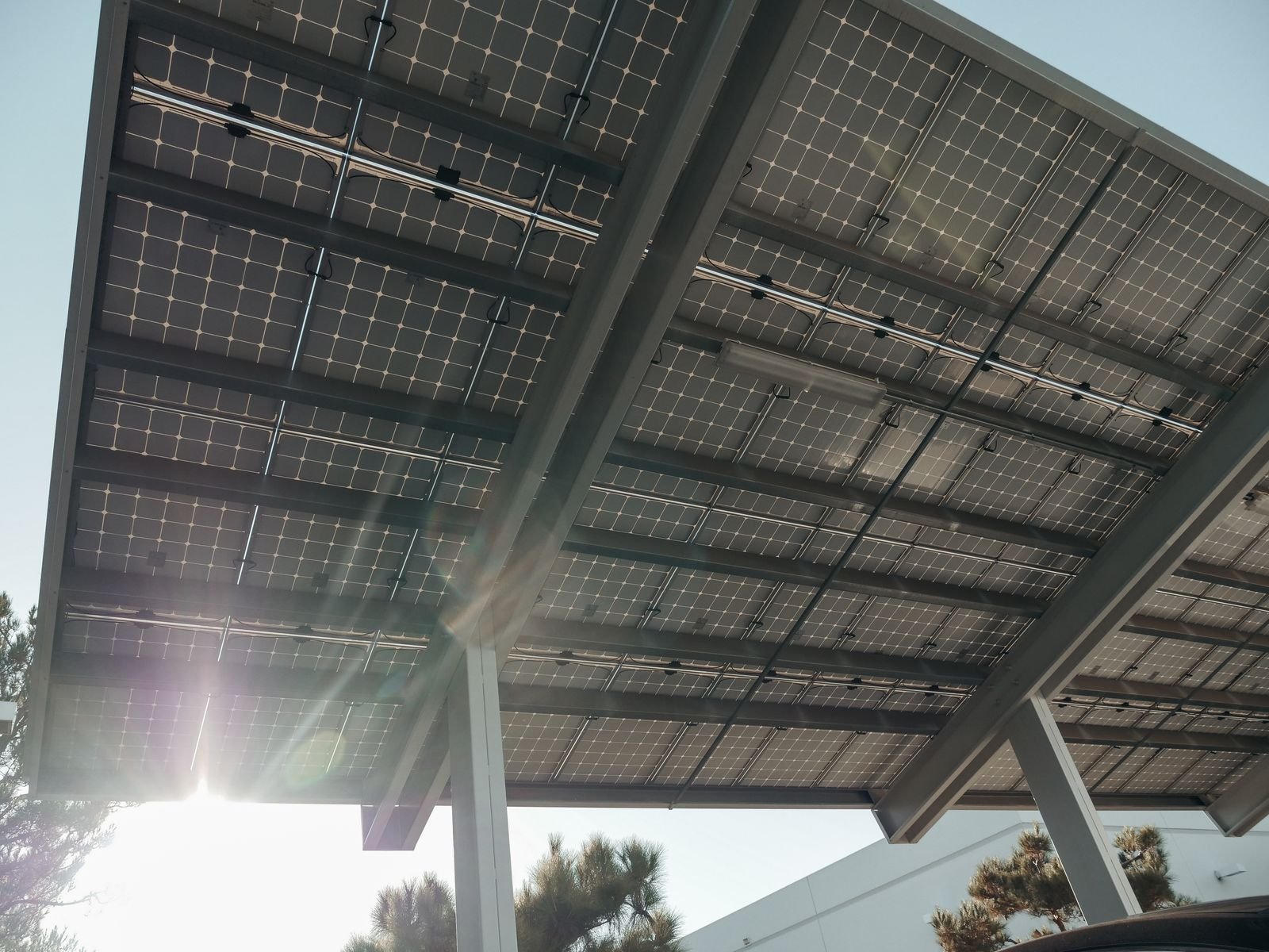
A monofacial array only cares about the front face. A bifacial array also collects light that bounces off the ground, the roof membrane or the structure itself and reaches the rear cells. Anything that blocks that path — a wide rail running down the centre of a panel, a deep purlin, a cable tray, a wall — removes part of the gain you paid for.
That single fact reshapes the whole design. Rail profiles get narrower, clamps get shorter, the array sits higher, and rows spread further apart. In practice, bifacial solar panel mounting is less about strength alone and more about strength with an unobstructed light path.
1. Keep the rear face as clear as possible
Start with the structure that touches the panel. Rear-side shading is caused by the mounting system itself far more often than by the site.
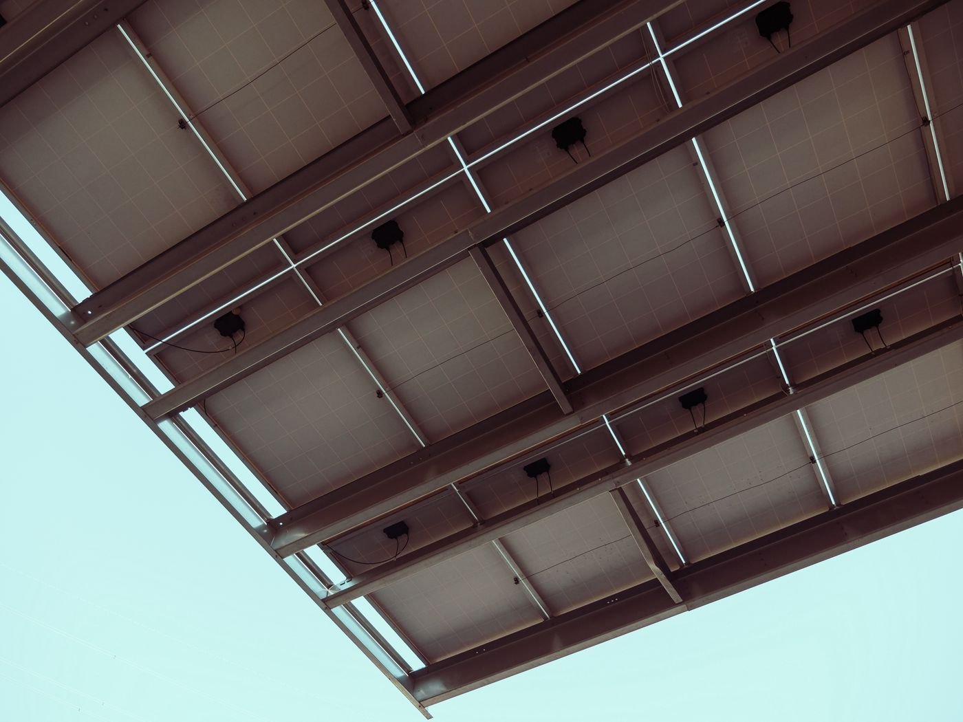
- Use two rails in portrait orientation rather than a single central rail. A centre rail throws a shadow straight across the middle of the rear face, which is exactly where rear cells do their work.
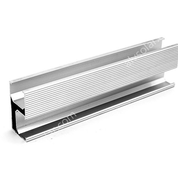
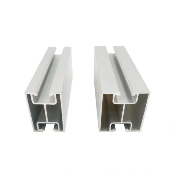
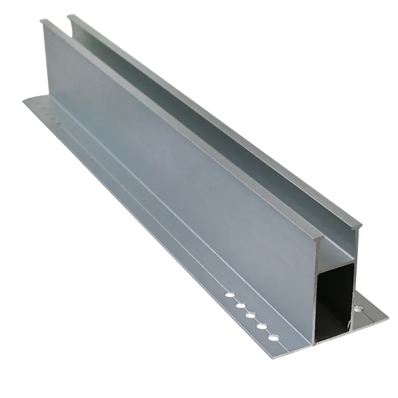
- Choose narrow, low-profile rails. A slim extrusion casts a thinner shadow than a deep C-section of the same strength.
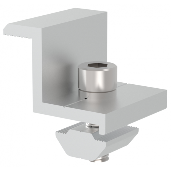
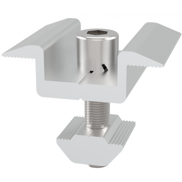
- Position clamps near the panel edges. End clamps at the frame edge shade almost nothing; long mid-clamps reaching into the panel area do.
- Keep cable trays and harnesses out of the panel footprint. Route DC cabling along the posts or under the beam line, not diagonally behind the modules.
- Avoid dark, wide structural members behind the array. Light-coloured or mill-finish aluminium reflects a little light back; dark painted steel absorbs it.
A simple rule used by many designers: if a structural element covers more than about 10% of the rear area of a module, it will measurably reduce the bifacial contribution. Rear-side shading is rarely modelled in standard software, so it has to be designed out on paper.
2. Set the mounting height deliberately
Height is the single most powerful variable in bifacial solar panel mounting. The lower the module, the smaller the ground area that can reflect light onto the back, and the more the ground plane itself shades the lower edge of the panel.
Industry guidance converges on a minimum of roughly 0.5 m from ground to the lowest edge of the module, with most commercial ground-mount projects landing between 1.0 m and 1.5 m. Research from NREL and field studies show the gain climbing steeply up to about 1 m, then flattening: beyond 1.5 m, extra steel usually costs more than the additional energy is worth.
| Mounting type | Typical clearance to lowest edge | Notes | | — | — | — | | Ground mount, utility scale | 1.0 – 1.5 m | Best balance of gain and steel cost | | Ground mount, high snowfall | 1.5 m + local snow depth | Prevents burial and edge shading | | Flat commercial roof | 0.15 – 0.20 m | Limited gain; airflow and cleaning matter more | | Elevated roof or canopy | 0.3 m + | Worth it only with a light-coloured surface below | | Carport / canopy | 2.5 m + | Driven by vehicle clearance, not by bifaciality |
Two practical additions: add the local snow depth to the minimum height, and check that the chosen height still allows safe cleaning and torque checks from the ground or a small platform.
3. Match tilt to albedo, not to habit
Bifacial yield depends on how much light reaches the ground beneath the array and bounces back. That reflected share is the albedo of the surface.
- Fresh snow: 0.80 – 0.90 (the best bifacial surface there is)
- White membrane or light concrete: 0.60 – 0.75
- Light gravel or sand: 0.35 – 0.55
- Dry grass: 0.20 – 0.30
- Dark soil, asphalt: 0.05 – 0.15
On a high-albedo site, a slightly steeper tilt exposes more of the rear face to the ground and can be worth 1° to 3° more than the latitude-optimised angle. On dark soil, steepening the tilt buys almost nothing, so the standard angle for maximum front-side yield stays the better choice. Remember that albedo changes with season — snow months behave nothing like summer — so model annual, not single-season, output. Seasonal field data published by IEA-PVPS is a useful reference for those assumptions.
4. Widen row spacing and lower the ground coverage ratio
In a multi-row array, the front row shades both the front and the back of the row behind it. Bifacial designs therefore run lower ground coverage ratios (GCR) than monofacial layouts: roughly 0.30 to 0.40 on high-albedo ground, 0.40 to 0.50 on typical grass or aged concrete.
Wider spacing costs land, so the trade-off has to be calculated per project. A useful check: compare the energy lost to rear shading against the cost of the extra land and steel. On cheap land with bright ground, wider rows usually win. On constrained sites, accepting a lower bifacial gain and keeping the GCR high is often the more profitable choice.
5. Choose rails, clamps and fasteners for the rear face
The hardware that grips a bifacial module has to respect glass-on-glass construction. Bifacial modules are typically heavier than framed monofacial panels, and many are frameless, so clamp pressure and position matter more.
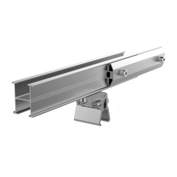
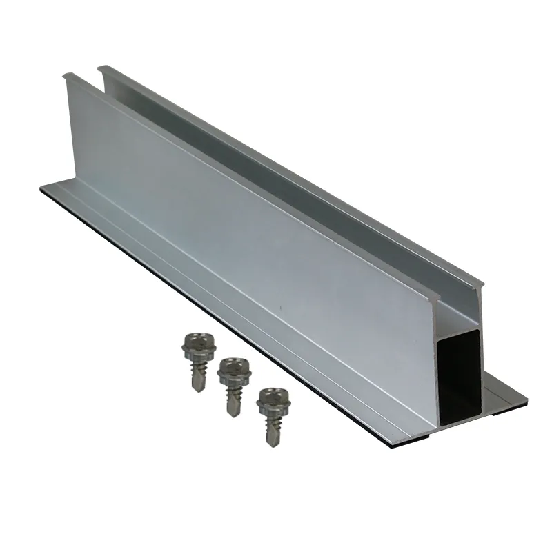
Use clamps rated for the module’s clamping zone, keep to the manufacturer’s torque specification, and confirm that the clamp body does not overhang the glass edge. Stainless-steel fasteners or properly coated hardware protect the connection in coastal and high-humidity sites. Our guide to solar panel mounting rails covers profile sizes and splice details in more depth.
6. Plan cabling, grounding and monitoring for the back
Everything electrical lives behind the panel. That makes cable management a bifacial design issue, not an afterthought:
- Run strings along the beam line, fixed with UV-resistant clips.
- Keep connectors and junction boxes inside the shadow-free zone under the rail, not loose against the rear glass.
- Bond every module frame or clamp to the structure with a listed grounding clip; frameless modules need clamps with an integrated bonding pin.
- Leave service loops short enough that they cannot flap against the rear surface in wind.
7. Verify loads, corrosion and certification before you buy
A taller, wider-spaced structure carries more wind moment at the post base. Run the structural check with the actual site wind speed and snow load — the same method used for any high-wind and snow-load design, with the added height taken into account.
Confirm as well that the supplier can document the coating or anodising thickness, the alloy temper, and the test reports behind the claimed 25-year life. Standards such as IEC 62548 for array design and AS/NZS 1170.2 for wind actions are the usual benchmarks international buyers ask for.
Quick specification checklist
Before you release a purchase order for a bifacial project, confirm these seven points in writing:
1. Rail count and position keep the rear face clear of structural shadows. 2. Lowest-edge height is at least 0.5 m, and 1.0 – 1.5 m on ground mounts. 3. Tilt reflects the actual albedo of the site, not a default angle. 4. GCR and row spacing are stated, with the shading assumption behind them. 5. Clamps are rated for the module type and torque value is specified. 6. Cabling and grounding are routed outside the rear light path. 7. Wind and snow loads are calculated for the final height and span.
Bifacial solar panel mounting rewards planning. Every centimetre of clearance, every narrowed rail and every extra metre of row spacing either adds harvestable light or adds cost — and the projects that perform are the ones where that trade-off was decided before the first post was driven.
SSS
How high should bifacial panels be mounted?
At least 0.5 m above the ground, with 1.0 – 1.5 m being the practical sweet spot for commercial ground mounts. On roofs, 0.15 – 0.20 m is common but delivers only a small bifacial gain.
Can bifacial panels be mounted on a standard roof?
Yes, but the gain is usually modest because roof racking sits close to the surface and dark shingles absorb light. Bifacial modules make most sense on ground mounts, carports and light-coloured flat roofs.
Does bifacial mounting need special rails?
Not special, but narrower and better placed. Two rails in portrait orientation, slim profiles and edge-mounted clamps reduce rear shading without weakening the structure.